Pressure Distribution and Shallow Trench Septic Design in Central New York
Pump chambers, pressure-dosed laterals and shallow trench fields for lots with 2 to 4 feet of usable soil or long, flat or uphill fields. PE-stamped plans under NYS Appendix 75-A and the install.
Pump. Dose. Rest.
The numbers behind a pressure-dosed or shallow trench design.
A septic system with a pump chamber after the tank that pushes measured doses of effluent through small pipe with drilled orifices, so the whole field is loaded evenly and then rests. Appendix 75-A requires at least 1 psi at the far end of each lateral.
Appendix 75-A requires pressure distribution in mounds and absorption beds, dosing or pressure in raised systems (with a narrow gravity exception), dosing once trench length reaches 500 feet, and alternate dosing at 1,000 feet. A pump is also needed whenever the field is uphill of the tank.
A conventional trench field set near the surface, used where there is at least 2 but less than 4 feet of usable soil. Trench bottoms stay in the original soil, and fill matching the native soil, no more than 30 inches deep including topsoil, covers them.
One full day of design flow above the alarm level, or duplex pumps with individual alarms instead. For a 3-bedroom house designed at 330 gallons per day, that is 330 gallons of reserve above the alarm.
No. Appendix 75-A allows only pumps the manufacturer designates for sewage effluent, and the state handbook says sump pumps are not appropriate and will quickly fail.
The pump stops and effluent builds up in the reserve storage. The state handbook says to cut water use until power returns, and to limit the first pumping cycles to no more than the daily design flow with at least 2 hours rest between cycles.
Yes. The far ends of the laterals can clog, so the design includes turn-ups for flushing, and the handbook says to flush laterals when the septic tank is pumped or as needed. Floats and the alarm should be checked too.
Pressure distribution and shallow trenches, explained
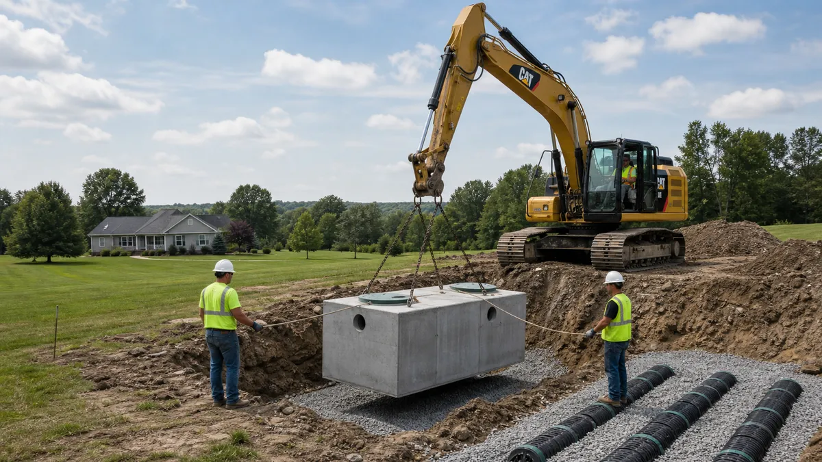
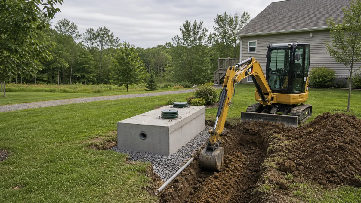
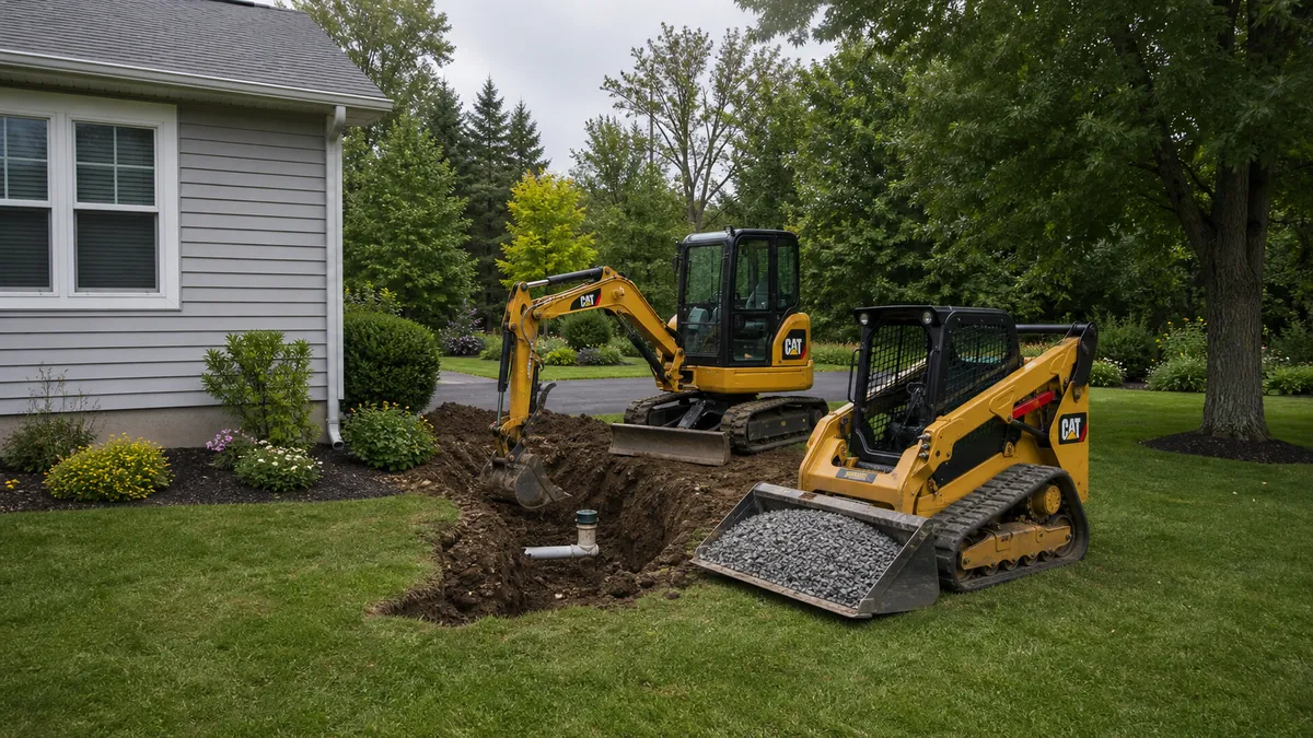
A pressure distribution system adds a pump chamber after the septic tank. Instead of letting effluent trickle down the first few feet of each trench, a pump pushes a measured dose through small pipe with drilled holes, so the whole field gets wet at once and then rests. A shallow trench system is a field whose trenches sit near the surface, with a thin layer of matching fill on top, for lots with only 2 to 4 feet of usable soil. The two often go together. Designs are prepared and stamped by a New York licensed Professional Engineer (PE). Backwell coordinates the design, the county submittal, and the install of the tanks, pump, controls, and field.
When pressure distribution or dosing is required
Under 10 NYCRR Appendix 75-A and the NYS design handbook, a pump or siphon is not optional in these cases:
- Mounds: a pressure distribution network is required in every mound.
- Absorption beds: pressure distribution is required; the county may allow siphon dosing on specific sites.
- Raised systems: siphon dosing, pump dosing, or pressure distribution is required, unless the county runs a full evaluation, approval, and inspection program and at least 2 feet of 5 to 30 minute fill sits under the trenches.
- Long fields: dosing is required when total trench length reaches 500 feet, and alternate dosing to two sections at 1,000 feet.
- Sand filters: pressure distribution or dosing once the filter reaches 300 lineal feet of distributors or 900 square feet of filter area.
Appendix 75-A also says dosing or pressure distribution is recommended for all systems, because the rest period between doses keeps the trenches aerated and makes the field last longer. The handbook adds that pressure distribution helps in slowly permeable soils and in alternative systems where even loading matters.
Dosing vs pressure distribution
The state handbook draws a clear line between the two:
- Dosing uses a pump or siphon to send a dose to a distribution box, and from there the effluent runs by gravity into perforated laterals laid as level as possible. Each dose should be 75% to 85% of the volume of the distribution pipe network.
- Pressure distribution pumps effluent through a small-diameter pipe network and out through orifices under low pressure. A distribution box is never used with pressure distribution, and every lateral is laid level and capped or looped at the end.
- Timed dosing runs the pump on a timer instead of a float, spreading the day's flow into smaller doses. The handbook calls it the best method of controlling distribution, generally targeting 12 doses a day, and requires the pump chamber to have enough surge capacity to hold peak flows.
Pressure network design numbers
A pressure network is a small hydraulics problem. The state numbers the design works to:
| Item | Requirement |
|---|---|
| Pressure pipe diameter | 1.5 to 3 inches under Appendix 75-A (the handbook lists 1 to 3 inches) |
| Pressure at the far end of each lateral | At least 1 psi, which equals 2.3 feet of head |
| Lateral length | Up to 100 feet from the manifold, 100 feet each way from a center manifold |
| Orifice flow difference along a lateral | Within 10% of the far-end orifice flow |
| Manifold head difference | Within 10% of the far-end head |
| Net dose volume | About 5 times the lateral pipe volume, and not over 20% of the daily design flow per dose |
Before backfill the network is tested by turning the orifices up and running the pump. The height the water shoots, the "squirt height," shows the pressure at each lateral. Over time the far ends of laterals can clog with biological growth and solids, so the handbook calls for flushing provisions: turn-ups at the distal ends, Schedule 40 pipe recommended for the network and turn-ups, sleeves to protect them, and caps sealed against leaks. Laterals can also have individual valves near the manifold, set in low-profile boxes.
The pump chamber
The pump chamber is where most of the code lives. Appendix 75-A and the handbook require:
- An alarm, audible or visual, in a place the owner will notice, to signal a pump failure.
- Reserve storage of one full day of design flow above the alarm level, or a duplex pump setup with individual alarms. That reserve is what keeps the house usable while a failed pump is replaced. The handbook notes high groundwater or shallow rock can be a reason to choose duplex pumps.
- No overflow pipe on a pressure distribution chamber.
- Effluent pumps only. Only pumps designated by the manufacturer for sewage effluent. The handbook warns that sump pumps are not appropriate and quickly fail.
- Explosion-proof controls in the dosing tank, and floats tested and set for the right dose volume.
- Buoyancy addressed in the design when the chamber sits below the high groundwater table, for instance by anchoring, and a watertight tank and piping.
- Locked covers at or above grade, and a pump that can be pulled without entering the tank.
- Freeze protection for a force main that is not below frost depth. Draining it back to the chamber between doses, often with a weep hole downstream of the check valve, is preferred over insulating.
After a power outage or a pump failure, the handbook says the volume pumped per cycle should not exceed the daily design flow, with at least a 2-hour rest between cycles, so the field is not flooded with everything that built up in the chamber.
Shallow trench systems
Appendix 75-A, section 75-A.8(e), allows shallow absorption trenches where there is at least 2 feet but less than 4 feet of usable soil or separation to boundary conditions. The design rules:
- At least 2 feet of separation between each trench bottom and groundwater, bedrock, or tight soil.
- Trench bottoms never above the original ground surface. The handbook prefers them at least 6 inches into the original soil.
- Fill with the same permeability as the original soil, and never more permeable. Fill depth, including 6 inches of topsoil, no more than 30 inches above original grade.
- Fill carried at least 6 feet out from the trench sidewalls, then tapered no steeper than 1 vertical to 3 horizontal.
- Trench length sized on the perc rate of the original soil, with perc holes at trench depth (or 6 inches below grade if the trenches sit between grade and 6 inches down).
- A diversion ditch or berm uphill on any sloped site, and heavy equipment kept off the absorption area.
One setback detail is specific to shallow trenches. For fill systems, separation distances are normally measured from the toe of the fill, but the handbook says that when the trench bottom is at least 6 inches into existing soil, they are measured from the trench sidewall. That can be the difference between fitting on a lot and not.
Onondaga County's design guidelines add a testing point: the designer has to show the required 2 feet of suitable soil exists, with a perc test at that depth, before the shallow system is sized at the shallower trench depth.
What the health department checks
On a pumped system the county reviewer wants to see the hydraulics, not just the field: pump selection with the head and flow, dose volume, float or timer settings, the reserve storage or duplex pumps, the alarm, and the lateral and orifice layout. The handbook recommends that when pressure distribution is used, the design professional supervise construction, prepare an operating manual, and handle start-up, and that a design professional supervise and certify pump and siphon installation.
Timeline and cost
Pumped systems do not add a regulatory wait of their own; the clock is the testing season and the county review. If fill is used in a shallow trench system, it has to be stabilized before the trenches go in. On cost, the county fees are published ($310 Onondaga for a full application under 1,000 gpd, $125 Oswego, $500 Oneida). The extra hardware, a second tank, an effluent pump, controls, an alarm, and electrical, is what separates the price from a gravity field, and it all goes into one written price.
Related reading: mound design, raised bed design, conventional design, small lot setbacks, system types, and the septic engineer hub.
Sources
- NYS DOH, 10 NYCRR Appendix 75-A, Wastewater Treatment Standards, Residential Onsite Systems (compilation effective 3/16/2016)
- NYS DOH, Residential Onsite Wastewater Treatment Systems Design Handbook (2012), posted by Onondaga County
- Onondaga County Health Department, Design Guidelines for Individual Sewage Systems (1999)
- Onondaga County Health Department, Fee Schedule
- Oswego County Health Department, Septic Plan Review
- Oneida County Health Department, Plan Review Fees (rev. 3/2022)
Regulatory figures on this page are taken from the documents listed. Rules change; the county health department reviewing the plan applies the version in force when the plan is submitted.
Other septic designs.
Tell us about the site.
Send the address. Estimate in 1 hour.
Free Written Estimate
Estimate in 1 hour.